Serial Peripheral Interface
- A synchronous serial data protocol that acts as an interface bus which operates at full-duplex where data can be sent and received simultaneously which was developed by Motorola.
- It uses separate lines for data and a shared clock to keep both master and slave to be in sync. The shared clock functions as an oscillating signal which tells the receiver when to sample the data bits on the data line. One bit of data is transferred in each clock cycle which means the speed of data transfer is being determined by the frequency of clock signal which is generated by the master, and the data is transmitted bit by bit.
- When the receiving slave detects the clock signal, it will get ready to read data bits on the data line. SPI is used in places where speed is important like flash memory (eg. SD cards), display modules, places where info updates and changes quickly (eg. sensors, thermometers), real-time clocks (RTCs), analog-to-digital converters, and many more.
SPI Interface
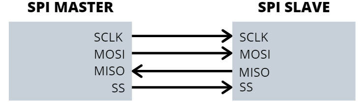
SPI is a synchronous data bus, which means that it uses separate lines for receiving and transferring data and a clock to keeps both sides in perfect sync and also a line which for addressing functions.
In total, the SPI bus will have a total of 4 lines which they use to communicate between the master and peripheral device which are:
MOSI
MISO
SCLK
CSS
MOSI and MISO
- The MOSI and MISO lines are the data lines where MOSI is responsible for transmitting data from the master to the slave and MISO is responsible to transmit data from the slave to the master.
- When the slave needs to send a response back to the master, the master will first generate a prearranged number of clock cycles first before the slave transmits data on the MISO line.
Compared to asynchronous serial where data is sent in either direction at any amount, the master knows how much data is being returned and when in SPI.
SCLK
- SCLK which is the clock signal is generated by the master to the slave to signal it to look at the data line to read data bits incoming.
- In SPI interfaces, there is only one master who is in charge of generating the clock signal to one or more slaves.
SS/CSS
- SS/CSS has the same functionality as chip select which is used as an addressing function. This signal is normally an active-low signal which is then pulled high to disconnect a slave from the SPI bus.
SPI Data Transmission
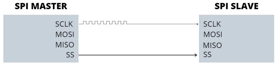
An SPI communication will typically start with:
- Master sending a clock signal and selecting a slave through the SS line.
- Master will send a logic 0 signal to select a slave as this line is on an active low signal.
- If a waiting period is required (eg. Analog to digital conversion) the master will be required to wait for a period of time before being able to send the clock signal.
- SPI is a full-duplex interface so both master and slave can send data to each other at the same time via the MOSI and MISO lines respectively and data is transmitted simultaneously between the master and slave. This will be synchronized by the serial clock. For example, these two operations will happen at the same time:
- Master sends data one bit at a time on the MOSI line = Slave Reads it
- (If a response is needed) Slave returns the data one bit at a time to the master on the MISO line = Master reads it
- SPI provides you with the flexibility to select the rising or falling edge of the clock to sample or shift the data.
- For the number of data bits to be transmitted, please do refer to your device datasheet as every device differs.
SPI Slave Selection
- As mentioned above, the SPI protocol first starts with the Master sending a clock signal and selecting a slave through the SS line. On the SS line, there are two ways in which the master can use to select a slave to receive or send data when there are multiple slaves involved
Regular Independent Slave Configuration
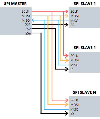
- Through this configuration, each slave will require a separate SS line.
- The master will activate a particular slave by making the particular slave SS line low while keeping the others high.
- Having two slaves activated at the same time is a serious problem as when two slaves are sending data on the same MISO line, data will be garbled and distorted.
- Once the particular SS line is low, the clock and data on the MOSI / MISO line will be available for the selected slave.
- Do note as slave devices increases, more and more SS lines will be required where more inputs and outputs will be required from the master device. So there will only be only a limited of slaves you can connect to your master device without any chip to multiply your SS outputs
Daisy-Chain Configuration
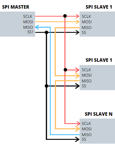
- For the daisy-chain configuration, it is slightly different compared to having individual SS lines. In this configuration, the slaves are tied together and data are transferred from one slave to another.
- The daisy-chain configuration involves a single SS line that goes to all the slaves involved where when the SS line is raised by the master, all slaves will be activated.
- For the daisy-chain configuration, the master will have to send enough data for data to overflow from the first slave all the way to the last slave as you want data to reach every slave.
- When using the daisy chain configuration, do note that the first piece of data you transmit will always end up at the last slave
- The daisy chain configuration is only used when the master is only needed to output data and not need to receive any data back.
- If you need to receive the return data from the slave device, you need to connect the MISO of the master device to form a closed loop.
- But for this to happen, you will have to send sufficient receive commands for the return data to pass through all the slaves again just like sending data before it can reach the master!
Clock Polarity and Clock Phase
- In SPI, there is no protocol for data exchange which limits overhead and allows high-speed data streaming.
- The master can select the clock polarity and clock phase using a specific SPI mode where each mode control whether data is shifted in and out on the rising or falling edge of the data clock signal (known as clock phase) and when the clock will be idle at either high or low. (known as Clock polarity).
- By switching the clock polarity (CPOL) and clock phase (CPHA), it can form 4 unique modes to provide flexibility in communication between master and slave.
Here is a table listing the four modes of transmission:
| SPI Mode | CPOL (Clock Polarity) | CPHA (Clock Phase) | Output Edge | Data Capture |
|---|---|---|---|---|
| 0 | 0 | 0 | Falling | Rising |
| 1 | 0 | 1 | Rising | Falling |
| 2 | 1 | 0 | Rising | Falling |
| 3 | 1 | 1 | Falling | Rising |
Advantages and Disadvantages of using SPI
Advantages of using SPI
- Support full-duplex communication, which means data can be transmitted and received at the same time.
- Better signal integrity, supporting high-speed applications.
- The hardware connection is simple, only four signal lines are needed (some applications can be reduced to three).
- No transceiver required.
- The slave device does not need to address.
Disadvantages of using SPI
- Short transmission distance.
- There is no flow control specified, and no acknowledgement mechanism confirms whether data is received, unlike I2C.
- More Pin ports are occupied, the practical limit to the number of devices.
- No form of error check unlike in UART (using parity bit).
- Interrupt operation can only be done through additional signal lines.
- Only 1 master.
www.seedstudio.com